Infrared Photography
This introduction to infrared photography, and its value as a non-invasive technique for revealing hidden information in historic items, was written by Jonathan Jackson of IDP in 2005.
Infrared and IDP
From the outset IDP has seen the use of infrared and other specialist photographic and image manipulation techniques. Digital infrared photography is a valuable tool in the arsenal of the digital photographer, adding value and increasing knowledge and understanding of an object’s history and usage. It cannot always produce the results we would hope for but the technique is non-destructive, so even if it reveals only small amounts of hidden or obscured information, it is worth the effort.

Infrared imaging and photography can reduce the need for invasive and expensive conservation and cleaning, helping to maintain the historical integrity of the original object virtually removing wear and tear by digital means.
What is Infrared?
Visible light is made up of electromagnetic waves, or put another way, vibrations of electric and magnetic fields. Electromagnetic waves travel at the speed of light.
In layman’s terms – 300 million metres per second – 669.6 million miles per hour.


Each and every electromagnetic wave produces or exhibits a unique frequency and wavelength associated with that frequency. Every electromagnetic wave is classified according to their characteristic frequency forming what is commonly referred to as ‘The Electromagnetic Spectrum’. Most of the electromagnetic spectrum is invisible. The highest frequencies are gamma rays, x-rays and ultraviolet light. Radio, microwaves and infrared radiation populate the lower frequency areas of the spectrum. Visible light falls within a very narrow band between ultraviolet and infrared.

The colour light spectrum forms the part of the electromagnetic spectrum that we use in photography. It consists of the visible light spectrum plus ‘ultra violet’ and ‘infrared’ light.

A normal functioning human eye will respond to wavelengths from around 400 to 700nm (nanometers), although in some cases people may be able to perceive wavelengths from 380 to 780nm.


The human eye typically has its maximum sensitivity at around 555nm, the green/yellow region of the colour light spectrum when light adapted.
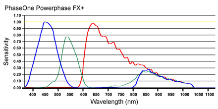
A standard digital camera imaging chip generally has a sensitivity of between 350nm and 1100nm.


With many digital cameras there is an infrared blocking filter built in to the camera lens to remove sensitivity to most infrared radiation. This filter is called a CCD, or Charge Coupled Device. It is a light sensitive solid state electronic silicon wafer containing pixels, used in cameras in place of film.
Camera backs such as the PhaseOne Powerphase FX+ have CCD sensors that are highly sensitive to infrared light and require a blocking filter to be used for conventional photography. For the infra-red photographer this provides a convenient opportunity for capturing high quality, high resolution images, combined with the ability to fine tune capture specifications.
Sources of Infrared
In order to produce infrared images a source of light capable of generating infrared radiation is required. The greater the infrared source the greater the contrast in the final image. Consideration needs to be given to the object being photographed as many sources of infrared also produce large amounts of unwanted and potentially damaging heat.
Many common sources of light emit infrared. The most common light sources are sunlight, lasers, tungsten and tungsten halogen lamps. The most usable and controllable sources of infrared are tungsten lights or electronic flash.

Daylight is a very unpredictable source of infrared with its ever changing spectral qualities brought on by variations in weather and atmospheric conditions such as haze.
Tungsten and tungsten halogen lamps produce high quantities of infrared. This however is traded with the potentially high heat levels associated with such lights.


Electronic flash, both in studio and on camera, provides a high output of Infrared combined with lower heat emissions.
Fluorescent lights and light units produce very low levels of usable infrared light. These lights also produce very little heat in comparison to tungsten lighting.

Light Control and Filtration
Once a light source has been identified, filtering the light will have the greatest effect on the final image. In most cases the filtering will be carried out on or in camera. There are many off-the-shelf filters available from Kodak, B+W, Schott and Hoya for example.
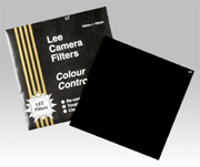
These filters are generally supplied as optical resin or gelatin based squares. Simple filters such as a Wratten 87 series will cut light transmissions out at below 700nm, allowing light transmission from 700nm through to 3000nm and beyond
Use of a narrow band filter can isolate small elements or selections of the spectral range. Controlling the transmission of specific wavelengths of light allows the photographer to capture information that can otherwise become lost or confused.

Narrow band filters generally have transmission values of between 10nm to 40nm either side of the marked rating, dependant on specifications.
For example:
A 900nm filter will allow light transmission from 860nm to 940nm
A 950nm filter will allow light transmission from 910nm to 990nm
Having a range of filters available at different cutoff points allows the user flexibility when photographing. Information can become visible where least expected.
Filtering of the light source is also possible for recording infrared images. In reality this would mean working in near total darkness and therefore is not really practical in most studios.

A key point of filtering is that no extraneous or unfiltered light should be allowed to enter the camera. It is therefore an advantage to have optical filters that attach either to the front or the back of the camera lens.
Focus and Exposure
Correct and sharp focusing is vital to producing usable end results, as it is in all areas of photography. Infrared filtering can have a great effect on how a lens performs. The point of focus shifts quite significantly under infrared conditions. Simply closing down the aperture and hoping that depth of field will compensate is not the solution.

The type of lens materials, coatings and construction will also influence the exact point of focus. These curves for crown and flint glass demonstrate that each glass focuses radiation of the same wavelength at different focal points. It also demonstrates that visible light is focussed at a different point from ultraviolet or infrared.
Digital infrared has a huge advantage over film as the results can be checked nearly instantaneously.

With an infrared filter in place it is not possible to focus as all visible light is blocked. Focusing must be done without the filter in place. Great care needs to be taken when attaching and removing the filter so as to not disturb any camera settings, especially relevant when using 5×4 cameras.

In a studio environment, focus compensation can be applied after running a few tests to determine the amount of focus shift required. A focusing block using a stepped wedge with increments of a known value can help provide the compensation value that needs to be applied. Focus correction can be applied in a number of ways depending upon the style of camera used. With 5 x 4 monorail or studio type cameras adjusting the lens or ‘film’ plane by the amount indicated by a focusing block / wedge helps maintain integrity of magnification ratios. Alternatively moving the object or camera in relation to one another. Focusing through a simple red filter can in some cases produce the required compensation.
Exposure with infrared can be quite prolonged. Again the advantage with digital photography is that there is no wasted film and the results are almost instantly available.
As a starting point by choosing a high sensitivity rating speeds the process, reducing the time that delicate objects are exposed to heat and light.
When producing an image, using the highest bit depth and highest resolution helps reveal the greatest information. Imaging in full Colour Range (RGB) and not Grey Scale increases the scope for image enhancement at a later stage. With sensitivity in the three channels there can be variations in the amount of information captured in the red, green, and blue channels. By targeting specific channels faint detail can be enhanced. The results may not be pleasing to the eye, but the process is directed at gathering information. The final image can always be de-saturated to make it more aesthetically pleasing.
Ideal aperture and exposure is all subjective, with many variables involved including filter type, lighting and most importantly the object. However the stronger the filtering the longer the exposure: filtering at 750nm will require a shorter exposure than that of a 1000nm filter.
Infrared in Practice
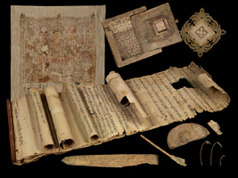
The equipment used by IDP for infrared imaging can be found in many institutions where digital imaging of documents is undertaken. At the heart of the system is a PhaseOne Powerphase FX+ digital scanning back. This type of camera back utilises a tri-linear sensor that scans the document in minute sections, building up the image to produce high resolution digital files.


The camera backs are mounted on DeVere 480 Vertical copy cameras. The camera is in turn secured to the wall and floor to prevent any movement during exposures.
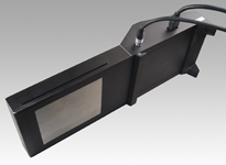
Lighting is provided by Elinchrom tungsten modelling lights. The lighting needs to be constant with a scanning back and flash, although a preferred choice of light source cannot be used.
Infrared filtering is by ‘cutout’ or narrow band filters in the range 750nm to 1000nm, which sit over the rear element of the camera lens, within the camera bellows. With the filters mounted inside the camera no unfiltered light can reach the scanning back.
Examples
Example 1: IOL Tib J 76 Tibetan booklet cover
IOL Tib J 76 is a booklet containing a series of Buddhist prayers. The cover has an accumulation of everyday dirt, grease from handling and smoke from oil and butter lamps and is well used and worn. Infrared ‘cuts’ through dirt and worn surface to reveal text and traces of ink.


The colour images show that text is present but not easily readable under normal lighting and viewing conditions.

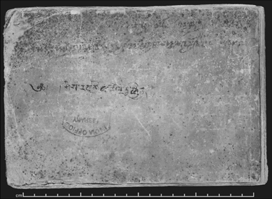
In producing infrared images we have increased the ease of reading the text. These images present the document in a form that is more usable and easier to study for the textual scholar than directly from the original manuscript. This in turn reduces further wear and tear.

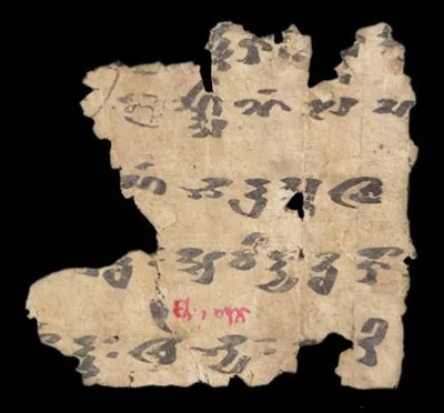
Example 2: IOL Tib J 738 Tibetan paper fragment
IOL Tib J 738 contains a treatise on divination, using the Tibetan ‘Mo’ system. This was clearly an important and well used document, which has led to the paper becoming darkened by age, handling and environmental factors.


At some point a gauze has been used to strengthen and stabilise the manuscript. The gauze has been removed but it has left an unfortunate ‘honeycomb’ pattern in the paper. Infrared has reduced the effect of the ‘darkening’ and softened the honeycomb effect of the gauze. The text becomes clearer and more readable.
Example 3: Or.8210/S.3454 Manuscript repairs and recycling
Or.8210/S.3454 is a scroll that has been repaired with paper strips to strengthen areas of wear and tear. The paper used in the repairs has been re-cycled from an old or redundant document. Such patches often have text or traces of text visible. The scroll is in much the same condition as originally found. These repairs reflect a style and technique that can be seen on many Dunhuang scrolls. Current conservation policy is that these patches should not be removed so as to maintain the integrity of the manuscript.
The text revealed can prove invaluable to historians and other scholars.


In this case infrared is used to ‘see through’ the paper and reveal the text. This technique is non-destructive and allows the patches to remain in situ. By reversing or inverting the image it is possible to read the text. Not all patches will yield results as can be seen from these images, but it reduces the need to remove the patches to confirm the presence or absence of text.
Example 4: Or.8211/1682 Kharoshti ‘Propeller’ woodslip
Wood was often used for all manner of documents as it was cheaper and, in places, more readily available than paper. Most woodslips are messages written in ink on thin pieces of wood.
This particular wooden document is unusually large, containing writing in Gandari using Kharosthi script, it measures just under one meter in length. Age and use have faded the inks making the text difficult to decipher. As it is a very large document it requires photography in multiple sections, which can then be digitally stitched together to reconstruct the document.


Infrared photography has been carried out in the same sectional manner. The infrared image has improved readability and revealed text not previously visible under normal viewing conditions.

A final complete image has been produce from four separate infrared images. The stitched image allows the texts to be easily read, while the individual images provide the ability to study individual areas in greater detail.

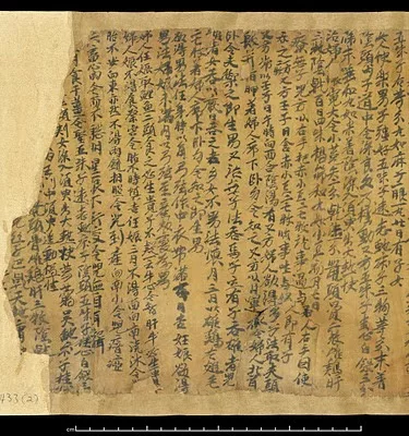
Example 5: Or.8210/S.5556 Damaged Chinese booklet
This booklet has been damaged where two pages have, over time, fused together and subsequently been forced apart by persons unknown. This has led to a layer of paper, complete with text, being torn from its original position and transfered to the opposite page. By imaging in infrared the text has been enhanced and can be digitally ‘removed’ and ‘reinstated’ in its original position.


Although time consuming, the process is relatively simple for anyone with a good level of Photoshop skills. The fragments of text are relatively easy to identify allowing the image to be built up like a textual jigsaw.


The final image shows how a fair amount of text has been re-created and reinstated. Although not perfect the process is non-destructive and non-invasive and the integrity of the original object has been maintained.
Case Studies
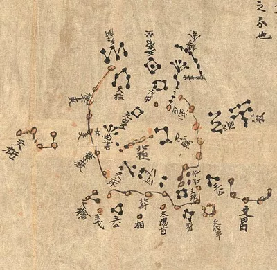
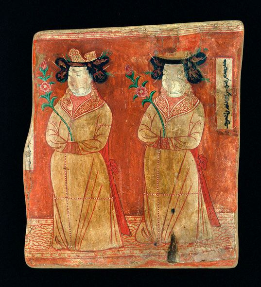
Case Study 1: Or.8212/1938
This manuscript presents a painting with light colour pigments on a very dark blue background. Infrared imaging has brought out the detail of the sketching of the painting, transforming a ‘barely there’ image to one that can be easily identified.


A beta radiograph (x-ray) has also been taken in the past to try to determine whether the pigments have metallic traces. The pigments however do not appear to be metallic in origin.
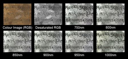
The process for imaging in infrared is very simple. However the choice of filter and post-capture manipulation will determine just how successful the final image will be.

1. Starting with an unmanipulated image you can see the difference each filter has on the subject. The full colour image has been desaturated to show how the manuscript would appear if we had only captured in grey scale.

2. The images are then colour corrected to remove colour casts. Each channel of colour information can hold differing amounts of detail depending upon the subject, and these can be enhanced individually. In this case no further information has been apparent so the colour has been neutralised to a neutral grey

3. By enhancing the contrast and brightness of the image the detail become very strong, pointing us towards a final choice of image. For this manuscript the image produced with an 850nm filter was chosen as this was felt to have captured the most useful detail of the drawing. Note that the desaturated image has failed to yield more detail. Under normal working the choice of filter would be made from past experience and further images produced only if the original filter choice failed to produce results.
| FILTER | SHUTTER SPEED | APERTURE | ASA | PIXEL DEPTH |
|---|---|---|---|---|
| 750nm | 40th/sec | f.11/16 | 400 | 16 bits/channel |
| 800nm | 40th/sec | f.11/16 | 400 | 16 bits/channel |
| 850nm | 30th/sec | f.11/16 | 400 | 16 bits/channel |
| 900nm | 20th/sec | f.11/16 | 400 | 16 bits/channel |
| 950nm | 15th/sec | f.11/16 | 400 | 16 bits/channel |
| 1000nm | 8th/sec | f.11/16 | 400 | 16 bits/channel |
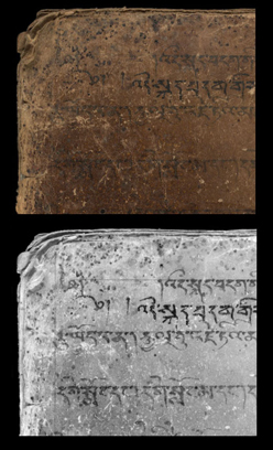
Case Study 2: IOL Tib J 9
The reasons for fading and wear of text will always be open to speculation but in many cases infrared can help to reveal and clarify text. IOL Tib J 9 exhibits a fairly common pattern of fading or wear. The surface appears dusty, has low contrast characteristics and is patchy in colour.

The top righthand corner has been subject to a minor repair. Below the repair is an area where the text is faded and the surface slightly scuffed. This is an area where we would hope to be able to reveal the lost characters of text using infrared photography.
Working down from the full colour image each Infrared filter has been used to try and reveal more information. As we work through the filters the contrast of the image becomes weaker.
The 1000nm image is nearing the very limits of the cameras sensitivity of around 1050nm. More information may be available but generally digital cameras are do not have a sensitivity tail beyond 1100nm so we are limited in how far we can go.
Each filter in step has revealed a little more information, however we would have liked to see more detail brought out. The only way we have of knowing that a manuscript will not react to infrared is to carry out the process of photographing and assessing the images.
By adjusting the brightness and contrast of the images it is possible to clean the image to enhance whatever information is present.
The images show that a few characters have been enhanced. There is however an area that appears to be ‘blocked’ that each filter has failed to bring through any text.


| FILTER | SHUTTER SPEED | APERTURE | ASA | PIXEL DEPTH |
|---|---|---|---|---|
| 750nm | 40th/sec | f.11/16 | 400 | 16 bits/channel |
| 800nm | 40th/sec | f.11/16 | 400 | 16 bits/channel |
| 850nm | 30th/sec | f.11/16 | 400 | 16 bits/channel |
| 900nm | 20th/sec | f.11/16 | 400 | 16 bits/channel |
| 950nm | 15th/sec | f.11/16 | 400 | 16 bits/channel |
| 1000nm | 8th/sec | f.11/16 | 400 | 16 bits/channel |


If you have feedback or ideas about this post, contact us, sign in or register an account to leave a comment below